C0-microSD Specifications
Compute and memory
| Component | Details |
|---|---|
| Signaloid C0 RISC-V-based SoC |
|
| FPGA | Lattice Semiconductor iCE40-UP5K:
|
| Non-volatile memory | Renesas AT25QL128A, 128 Mb (16 MiB) SPI flash |
| GPIO | Total of 13 GPIOs:
|
UxHw® capabilities
| Parameter | Value |
|---|---|
| Maximum representation precision | Athens-16 |
| Number of in-flight distributions | 600 (Athens-8) 288 (Athens-16) |
| I/O minimum latency (read / write)* | 0.8 ms / 6.0 ms |
| I/O maximum throughput* | 100 Mbit/s |
*I/O latency is measured on transactions of 512-byte blocks using the dd command.
Signaloid SoC Core details
| ISA | ABI | Operating frequency | Available memory |
|---|---|---|---|
| RV32I | ilp32 | 12 MHz | 128 KiB |
The Signaloid SoC is based on the open-source PicoRV32 project, extended to support a subset of Signaloid's UxHw technology and communication with the host over the SD interface.
The ISA/ABI is a per-module fact. If you want to use the RISC-V GNU toolchain,
build it for the rv32i / ilp32 configuration. See Programming and Toolchain
for instructions.
Electrical characteristics
| Parameter | Condition | Value |
|---|---|---|
| Supply voltage (VDD) | 3.14 V – 3.50 V | |
| I/O supply voltage (VDDIO) | LVCMOS 3.3 | 3.13 V – 3.46 V |
| I/O supply voltage (VDDIO) | LVCMOS 1.8 | 1.71 V – 1.89 V |
| I/O maximum drive rating | LVCMOS 3.3 | 8 mA |
| I/O maximum drive rating | LVCMOS 1.8 | 4 mA |
Power and current consumption
Current consumption is measured using a 3.3 V supply while adding two uniformly-distributed double-precision floating-point values (3.0 ± 0.6 and 5.0 ± 0.6) with UxHw technology.
| Parameter | Value |
|---|---|
| Minimum current | 4.96 mA |
| Average current | 5.18 mA |
| Maximum current | 7.43 mA |
| Power dissipation | < 30 mW |
Recommended operating conditions
| Parameter | Value |
|---|---|
| Operating temperature | −40 °C – 85 °C |
| Typical operating temperature* | < 35 °C |
*Measured after 30 minutes of continuous operation running a typical workload in an open-lid microSD slot at 24 °C ambient temperature.
Functional block diagram
The Signaloid C0-microSD SoM is based on the Lattice Semiconductor iCE40 FPGA, and contains 128 Mbit of serial NOR flash for storing bitstreams, firmware, and user data. The device also features two on-board LEDs, one red and one green, connected to the FPGA.
Pinout
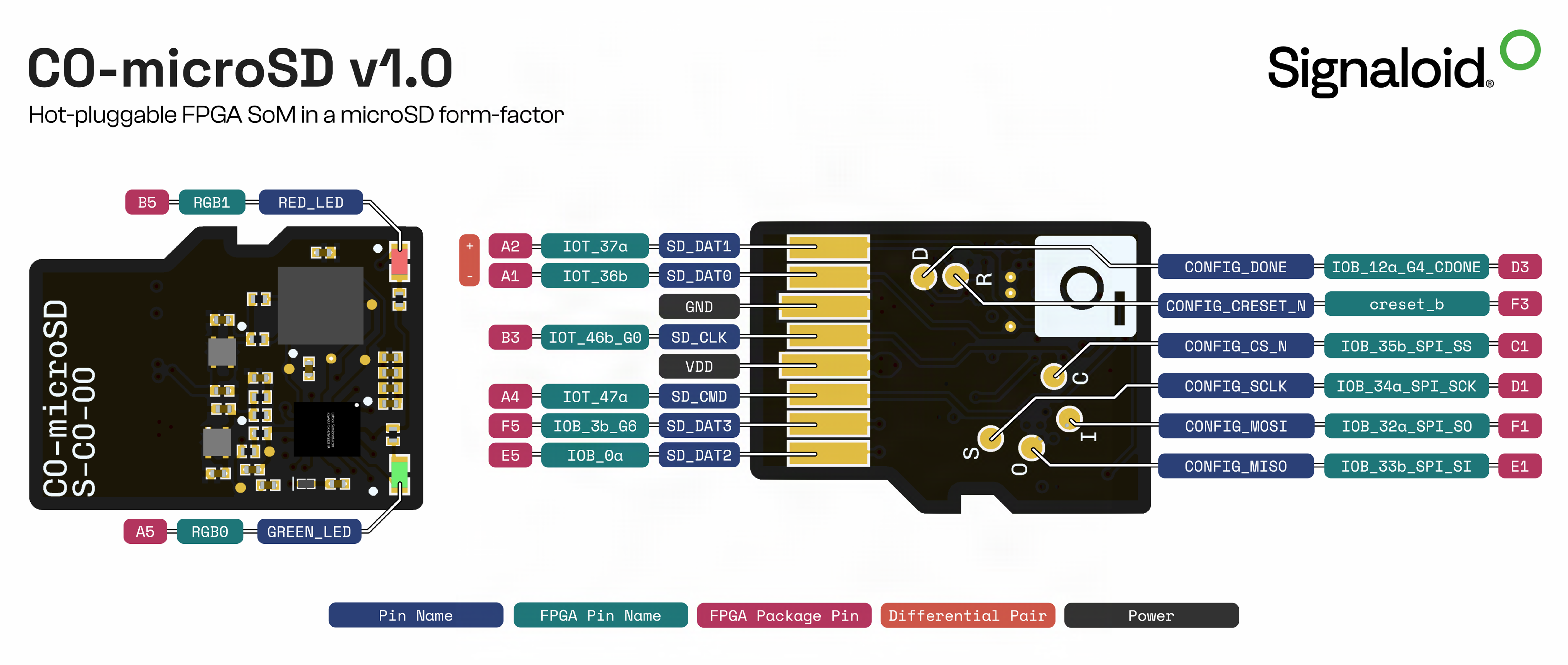
| Number | Pin name | FPGA pin | Standard | Description |
|---|---|---|---|---|
| 1 | SD_DAT2 | E5 | LVCMOS 3.3 | GPIO pin connected to the SD bus DAT2 |
| 2 | SD_DAT3 | F5 | LVCMOS 3.3 | GPIO pin connected to the SD bus DAT3 |
| 3 | SD_CMD | A4 | LVCMOS 3.3 | GPIO pin connected to the SD bus CMD |
| 4 | VDD | - | - | Supply voltage |
| 5 | SD_CLK | B3 | LVCMOS 3.3 | GPIO pin connected to the SD bus CLK |
| 6 | VSS | - | - | Supply ground |
| 7 | SD_DAT0 | A1 | LVCMOS 3.3 | GPIO pin connected to the SD bus DAT0 |
| 8 | SD_DAT1 | A2 | LVCMOS 3.3 | GPIO pin connected to the SD bus DAT1 |
| 9 | CONFIG_SCLK | D1 | LVCMOS 1.8 | Clock pin of SPI configuration port |
| 10 | CONFIG_MISO | E1 | LVCMOS 1.8 | MISO pin of SPI configuration port |
| 11 | CONFIG_MOSI | F1 | LVCMOS 1.8 | MOSI pin of SPI configuration port |
| 12 | CONFIG_CSn | C1 | LVCMOS 1.8 | Chip select of SPI configuration port (active low) |
| 13 | CONFIG_CRESETn | F3 | LVCMOS 1.8 | FPGA reset pin (active low) |
| 14 | CONFIG_DONE | D3 | LVCMOS 1.8 | Configuration Done pin |
| 15 | GREEN_LED | A5 | LVCMOS 3.3 | Open-drain green status LED |
| 16 | RED_LED | B5 | LVCMOS 3.3 | Open-drain red status LED |
- Pins 1–8 are the standard microSD interface.
- Pins 9–14 form the SPI configuration port used by an external programmer for factory/recovery programming.
Dimensions and package
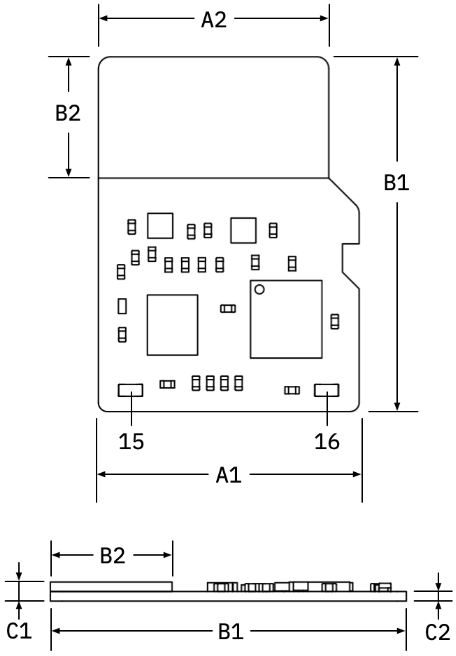
Overall dimensions: 11.0 mm × 15.0 mm × 0.8 mm.
| Dimension | Typical | Tolerance | Unit |
|---|---|---|---|
| A1 | 11.0 | ± 0.2 | mm |
| A2 | 9.7 | ± 0.2 | mm |
| B1 | 15.0 | ± 0.2 | mm |
| B2 | 9.9 | ± 0.2 | mm |
| C1 | 0.8 | ± 0.2 | mm |
| C2 | 0.4 | ± 0.2 | mm |
Next steps
- Design-In Guide, applying these figures to a host board.
- Compatibility, the SD host controllers and platforms tested with the module.
- Benchmarks, measured UxHw speedups against equivalent Monte Carlo workloads.
- Handling and ESD precautions, keeping the module within these conditions in the lab and in the field.