C0-microSD Modes and Custom Bitstream
The C0-microSD doubles as an open FPGA development board. In addition to the Signaloid SoC coprocessor mode, it supports a bootloader mode, mode switching, and custom user bitstreams, taking advantage of the iCE40 warmboot capability to reconfigure the FPGA from multiple stored images.
Modes of operation
The C0-microSD has three distinct modes of operation, also called active configurations:
- Bootloader mode: flash custom bitstreams, update the C0-microSD firmware, and flash user data to non-volatile memory.
- Signaloid SoC mode: load and run C/C++ applications on the Signaloid SoC, optionally using UxHw® technology.
- Custom user bitstream mode: load the latest custom user bitstream onto the device.
Modes 1 and 2 are used with a host device that communicates over the SD interface. Mode 3 is for using the C0-microSD as a standalone FPGA module.
The built-in Bootloader is always the first configuration to load. Following the boot order logic below, it either stays in Bootloader mode, switches to the Signaloid SoC configuration, or loads the Custom User Bitstream.
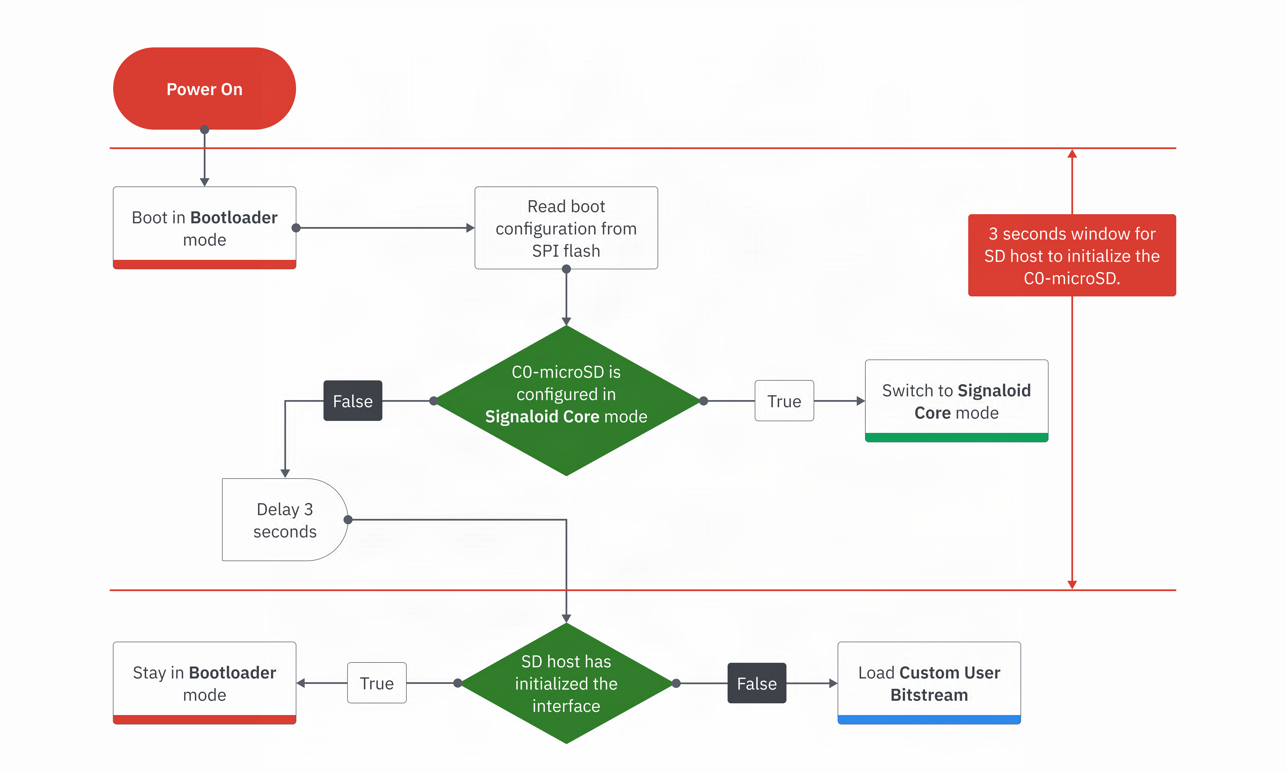
Identifying the active mode
When the C0-microSD is powered on and connected to a host:
- Bootloader mode: the red LED is solid.
- Signaloid SoC mode: the green LED is solid.
When powered on without a host present, the C0-microSD loads the Custom User Bitstream. LED behavior is then entirely determined by that bitstream.
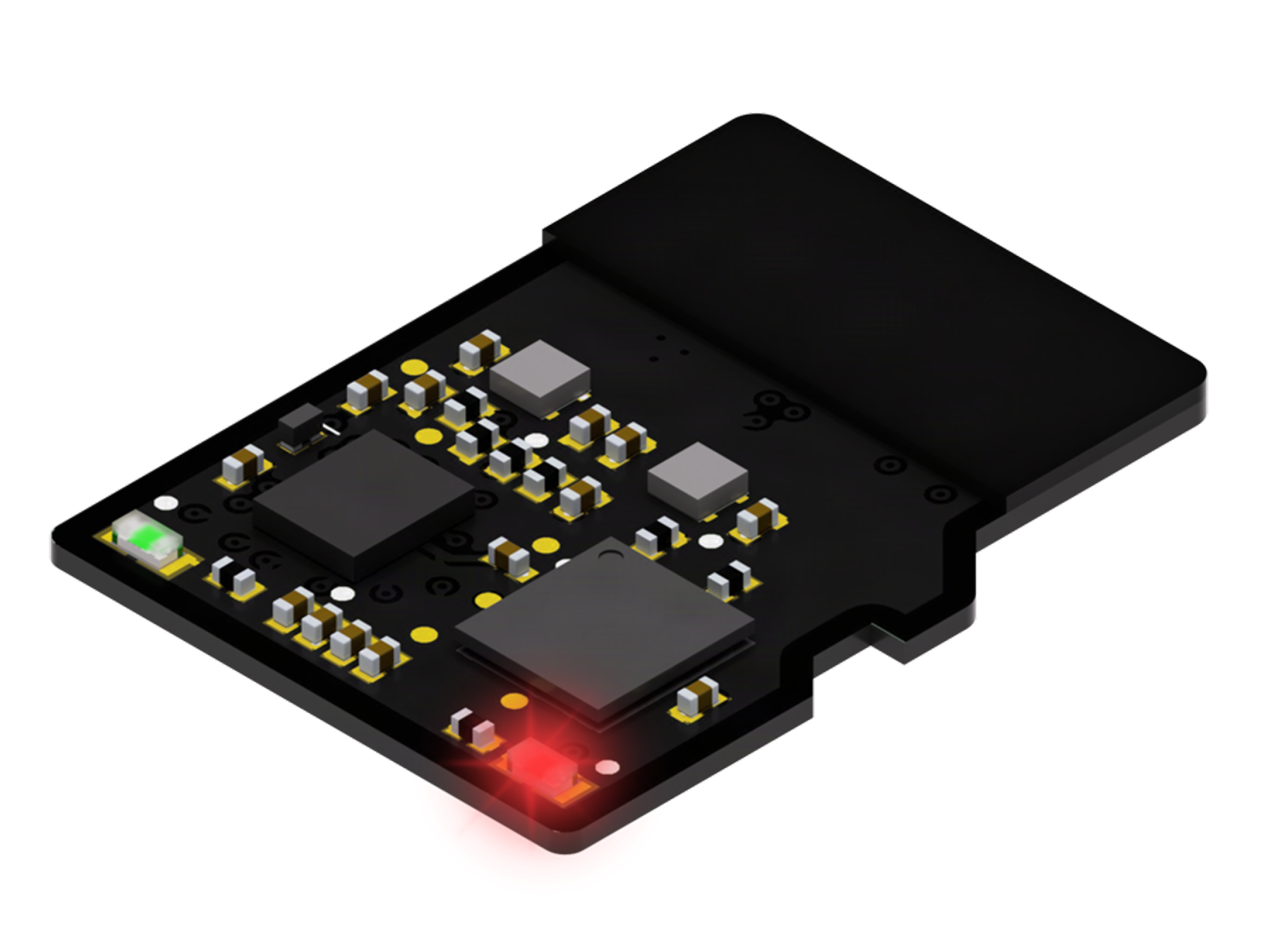 | 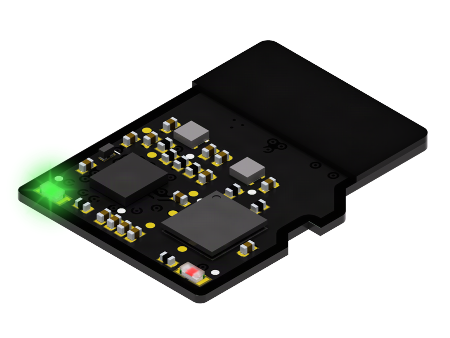 |
|---|---|
| Bootloader mode (solid red LED) | Signaloid SoC mode (solid green LED) |
Switching between modes
Switching between modes 1 and 2 requires writing to a predefined offset over the SD
interface. The C0-microSD stores the new setting in its on-board SPI flash and enters the
SWITCHING state. You must power-cycle the device for the change to take effect. Once in
the SWITCHING state, the LED that was not solid begins to blink, indicating the mode the
device will boot into next.
For the step-by-step procedure, see
Switch Between Operation Modes.
Programmatically, write the 4-byte ASCII word SBLD to
BOOTLOADER_SWITCH_CONFIG_OFFSET.
Bootloader and addressing
In Bootloader mode, you communicate with the device through block read and write operations at the following flash address offsets:
| Address space | Offset | Size | Operation | Description |
|---|---|---|---|---|
CONFIGURATION_ID_OFFSET | 0x020000 | 4 bytes | R | Active configuration ID |
CONFIGURATION_VERSION_OFFSET | 0x020004 | 4 bytes | R | Active configuration version |
CONFIGURATION_STATE_OFFSET | 0x020008 | 4 bytes | R | Active configuration state |
OTP_SECTOR_OFFSET | 0x022000 | 512 bytes | R | Non-volatile memory OTP sector |
BOOTLOADER_UNLOCK_OFFSET | 0x060000 | 4 bytes | W | Lock / unlock the bootloader |
BOOTLOADER_BITSTREAM_OFFSET* | 0x080000 | 512 KiB | R/W** | Bootloader bitstream region |
SIGNALOID_CORE_BITSTREAM_OFFSET* | 0x100000 | 512 KiB | R/W** | Signaloid SoC bitstream region |
USER_BITSTREAM_OFFSET* | 0x200000 | 512 KiB | R/W | Custom user bitstream region |
USER_DATA_OFFSET* | 0x280000 | 13 MiB | R/W | User data region |
BOOTLOADER_SWITCH_CONFIG_OFFSET | 0xF80000 | 4 bytes | W | Switch operation mode |
* Address space corresponds to on-board flash memory data. ** Address space must be unlocked before writing.
Key offsets:
CONFIGURATION_ID_OFFSETidentifies the active configuration as a 4-byte ASCII word,SBLDfor Bootloader andSSOCfor Signaloid SoC.CONFIGURATION_VERSION_OFFSETholds the version of that configuration, with the major version in its first two bytes and the minor version in its last two.OTP_SECTOR_OFFSETexposes the one-time-programmable sector holding the device serial number and UUID.BOOTLOADER_UNLOCK_OFFSET: the bootloader and Signaloid SoC bitstream regions are locked by default to prevent accidental overwrites that could render the device inoperable. Write the ASCII wordUBLDto unlock, and write anything else to lock again. The unlock does not survive a power cycle, so unlock the regions again after the module powers up.USER_DATA_OFFSET: a 13 MiB region for data or binaries. The Signaloid SoC initializes its memory by copying the first 128 KiB of this region before execution.
The SD interface mandates read and write support across the entire address space, which differs from the per-region operations above. For R regions, writes succeed but have no effect. For W regions, reads return invalid data. Any address space not listed above should be treated as not applicable (N/A): reads return invalid data and writes have no effect.
Write and erase semantics
The C0-microSD writes its flash in whole 4 KiB sectors. Writing a sector replaces all 4 KiB of it, so each write discards whatever the rest of that sector held.
Write whole sectors, starting at a 4 KiB-aligned offset and running from the first byte of the sector to the last. Two behaviors follow from that rule, and the module reports neither of them as an error.
- The module discards a partial sector. When a transfer ends before the last byte of a sector, the module writes nothing at all.
- The module does not preserve skipped bytes. Bytes that you leave out of the transfer do not keep the previous contents of the sector, so write every byte of every sector.
Most hosts meet this requirement without any effort on your part. A full-size SD host controller usually issues writes in whole aligned blocks of at least 4 KiB, so flashing from a computer behaves as you expect. A host that uses SD over SPI, typically a microcontroller, transfers 512 bytes at a time and must group eight of those transfers into each complete 4 KiB sector.
Never remove power while a flash write is in progress. A sector caught part way through an erase or a program holds neither its old contents nor its new contents.
Flash writes reach the device only in Bootloader mode. In Signaloid SoC mode nothing writes the flash, from the host or from the device application, apart from the mode switch described above.
Custom user bitstream flow
Using the C0-microSD as a programmable FPGA SoM does not require switching modes, you only need the device in Bootloader mode. Once powered on without an SD host, the bootloader loads the latest custom user bitstream. In this configuration the C0-microSD offers six configurable I/O pins (by repurposing the microSD pads) plus five test-pad I/O pins.
To flash a bitstream to the custom user bitstream region, use the
C0_microSD_toolkit.py script from the
Signaloid-Compute-Module-Utilities repository. On a macOS host with
the device at /dev/disk4:
sudo python3 C0_microSD_toolkit.py -t /dev/disk4 -b bitstream.bin
Flashing the custom user bitstream is the default operation of the script, so -b with no
mode flag targets the custom user bitstream region. See
Flash the C0-microSD
for the full flashing reference.
Example RTL designs, along with build and flash instructions, are in the rtl-examples/
directory of the
C0-microSD-Hardware repository.
Next steps
- Switch Between Operation Modes, the power-cycle sequence that moves the module between modes.
- Flash the C0-microSD, writing a bitstream or an application binary with the toolkit.
- Signaloid SoC, developing applications for the coprocessor mode.
- Custom FPGA Design, the toolchains for building your own bitstream.