Use an External Programmer to Flash the C0-microSD
You can flash the C0-microSD on-board SPI flash chip using an external programmer, and the iceprog toolkit, which is part of the IceStorm suite. This example uses the Tigard board, which can interface with SPI ports that operate at 1.8V and is compatible with the iceprog toolkit.
Do not attempt to manually flash the C0-microSD using an external programmer unless you know what you are doing. Overriding the Bootloader bitstream, the Signaloid SoC bitstream, or the first 512 KiB of the non-volatile memory may disable the bootloader and SD interface of the C0-microSD. Nevertheless, this method can be used to re-flash the Bootloader and Signaloid SoC in case they are corrupted, and bring the device to its initial state. You can find the official C0-microSD configuration bitstreams in the C0-microSD-Hardware repository.
-
Make sure that the
Tigardboard is configured correctly, with theTargetswitch set to1.8Vand theModeswitch set toJTAG/SPI(Figure 1). -
Connect the C0-microSD to the
Tigardboard as follows (Figure 1):C0-microSD Pin SilkScreen Tigard Board Pin Notes VDD- - Supply voltage of 3.3V must be externally provided VSS- GND Ground CONFIG_SCLKC TCK Clock pin of SPI configuration port CONFIG_DONED - Configuration done pin, not connected CONFIG_CRESETnR SRST FPGA reset pin (active low) CONFIG_MISOO TDO MISO pin of SPI configuration port CONFIG_CSnS TRST Chip select of SPI configuration port (active low) CONFIG_MOSII TDI MOSI pin of SPI configuration port The form-factor of the C0-microSD requires the use of special tooling for accessing the configuration pins mentioned above. We recommend one of the following methods:
- Using a probing system like PCBite from SensePeek.
- Using a data recovery jig like the iDili probe, the PC-3000 spider board, or something similar.
- Soldering small wires to the bottom pads. This is a cheap solution but might cause fitment issues if you do not thoroughly clean the pads from any remaining solder after you have completed the flashing process.
-
Connect a power supply of
3.3Vto the C0-microSD, make sure that the ground pins of the power supply and theTigardboard are tied together (Figure 1).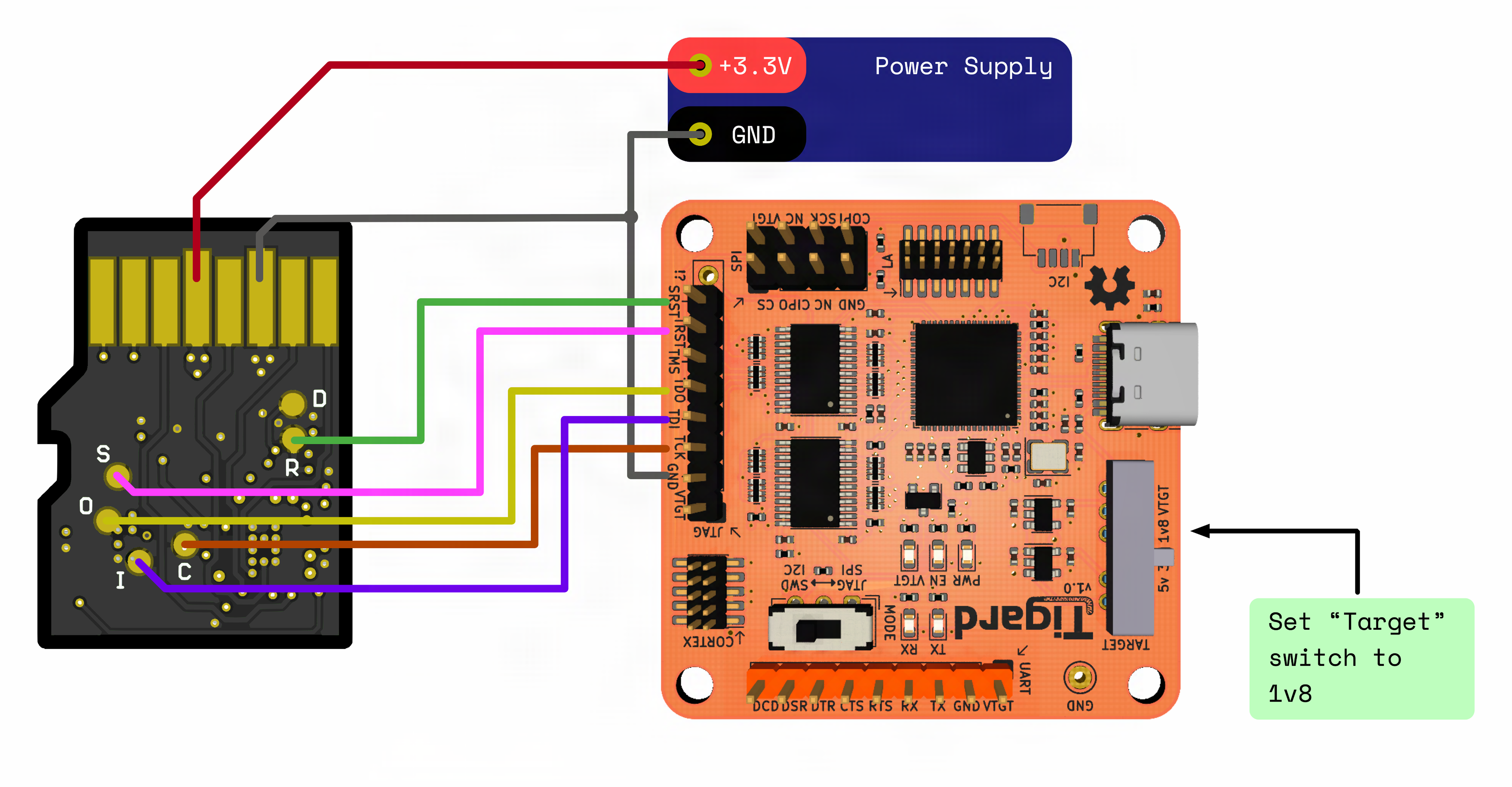
Figure 1: Tigard connection diagram using the pads located at the bottom layer of the C0-microSD. -
Use the
iceprogtool from theIceStormsuite to flash a new bitstream to the device. Assuming your bitstream is namedc0-microsd.binuse the following command and wait for the flashing process to finish:iceprog -I B -p c0-microsd.bininit..cdone: highreset..cdone: highflash ID: 0x1F 0x42 0x18 0x1F 0x42 0x18 0x1F 0x42 0x18 0x1F 0x42 0x18 0x1F 0x42 0x18 0x1F 0x420x18 0x1F 0x42 0x18 0x1F 0x42 0x18 0x1F 0x42 0x18 0x1F 0x42 0x18 0x1F 0x42 0x18 0x1F 0x42file size: 104157erase 64kB sector at 0x000000..erase 64kB sector at 0x010000..programming..done.reading..VERIFY OKcdone: highBye.A console message stating
VERIFY OKmeans that flashing the new bitstream was successful. You need to power cycle the device for the new bitstream to take effect.
Next steps
- Flash the C0-microSD, the ordinary flashing path over the SD interface.
- Custom FPGA Design, building the bitstream that you program this way.
- Pinout, the debug pads that the programmer connects to.
- Stuck? See Troubleshooting and FAQ.