C0-microSD Host Interface and Protocol
The C0-microSD communicates with a host over the SD interface, using either the 4-wire SD protocol or SD-over-SPI. When connected to a host, it presents itself as a 20.2 MB (19.3 MiB) unformatted block-storage device in both Bootloader mode and Signaloid SoC mode. See the shared SD interface concept for transport-level details.
All communication is achieved through host-initiated block read and write operations.
Communication over the SD interface uses block read and write operations, not the SDIO extension of the SD interface. No additional host drivers are required.
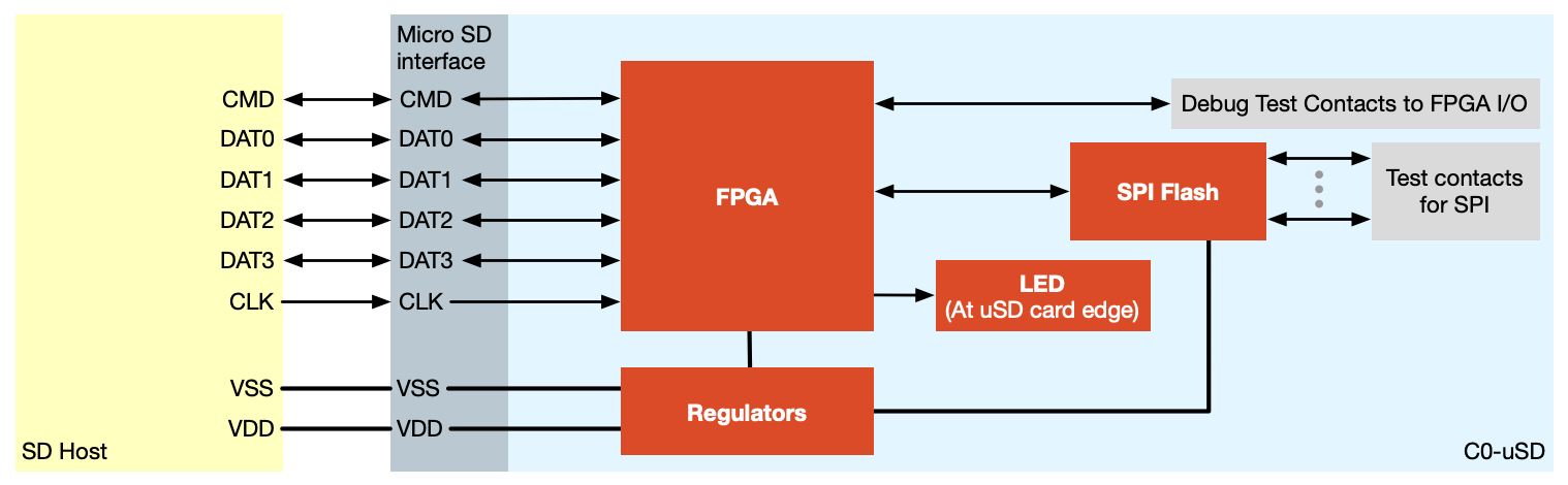
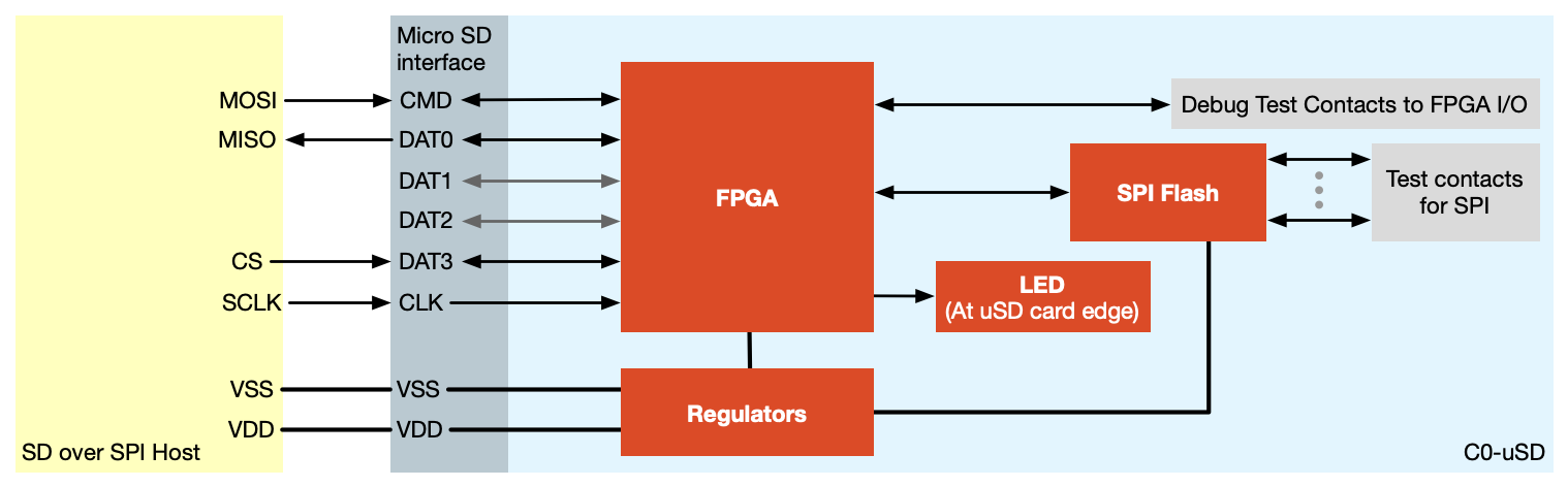
The C0-microSD connects to a host either over the 4-wire SD protocol or over SD-over-SPI:
 |  |
|---|---|
| 4-wire SD interface | SD-over-SPI interface |
MMIO memory map and registers
The C0-microSD realizes the shared
MMIO interfacing model in the
Signaloid SoC. On reset, the SoC copies the first 128 KiB of the flash user-data sector into
its internal SPRAM and begins execution from address 0x00.
The Signaloid SoC memory map, from the highest address at the top to the lowest at the bottom:
Communication registers (SoC-side addresses)
The device application accesses these registers as memory-mapped I/O:
| Register | Memory address | Size | Device operation | Reset value |
|---|---|---|---|---|
status | 0x40000000 | 4 bytes | W | 0x00000000 |
SoC Control | 0x40000004 | 4 bytes | W | 0x00000000 |
command | 0x40000008 | 4 bytes | R | 0x00000000 |
status: set by the device application to declare the application's current status.SoC Control: set by the device application to control SoC peripherals, and readable by the host over the SD interface.command: set by the host application, read by the device application, used to send commands to the Signaloid SoC.
The SoC Control register bits:
| Register bit | Usage |
|---|---|
| 31:2 | Reserved |
| 1 | Set CONFIG_DONE pin |
| 0 | Set on-board red LED |
All three registers reset to 0x00000000 when the module powers up, and all three are
volatile, so a power cycle returns them to that value. A status of 0 therefore reads the
same as the conventional waiting-for-command value, and command reads as 0 until the host
writes it, which is why 0 conventionally means no command. See
Power Cycles and State.
The specific values of the command and status registers are application-dependent.
Data buffers (SoC-side addresses)
| Buffer | Memory address | Size | Device operation |
|---|---|---|---|
MISO_BUFFER_ADDRESS | 0x40010000 | 4 KiB | W |
MOSI_BUFFER_ADDRESS | 0x40020000 | 4 KiB | R |
MOSI_BUFFER: Manager-Out, Subordinate-In: data sent from the host application to the device application.MISO_BUFFER: Manager-In, Subordinate-Out: data sent from the device application to the host application.
For the bootloader-mode flash address map, see Modes and Custom Bitstream.
Host-side addressing (Signaloid SoC mode)
The host addresses the Signaloid SoC's MMIO registers and buffers through SD-interface block
offsets. These differ from the SoC-side memory addresses documented in
MMIO memory map and registers.
For example, to write the command register from the host you use block offset 0x10000,
whereas the SoC application reads it at memory address 0x40000008.
| Address space | Offset | Size | Host operation | Description |
|---|---|---|---|---|
STATUS_REGISTER_OFFSET | 0x00000000 | 4 bytes | R | status register |
SOC_CONTROL_REGISTER_OFFSET | 0x00000004 | 4 bytes | R | SoC Control register |
COMMAND_REGISTER_OFFSET | 0x00010000 | 4 bytes | W | command register |
MOSI_BUFFER_OFFSET | 0x00050000 | 4 KiB | W | MOSI buffer |
MISO_BUFFER_OFFSET | 0x00060000 | 4 KiB | R | MISO buffer |
The following offsets let the host verify the active configuration and switch back to Bootloader mode:
| Address space | Offset | Size | Host operation | Description |
|---|---|---|---|---|
CONFIGURATION_ID_OFFSET | 0x00020000 | 4 bytes | R | Active configuration ID |
CONFIGURATION_VERSION_OFFSET | 0x00020004 | 4 bytes | R | Active configuration version |
CONFIGURATION_STATE_OFFSET | 0x00020008 | 4 bytes | R | Active configuration state (for example, SWITCHING) |
BOOTLOADER_SWITCH_CONFIG_OFFSET | 0x00040000 | 4 bytes | W | Switch operation mode (write SBLD, ASCII-encoded) |
The configuration-ID register identifies the active configuration as a 4-byte ASCII word.
| Value | Configuration |
|---|---|
SBLD | Bootloader |
SSOC | Signaloid SoC |
Any other value means the device is not a C0-microSD. The configuration-version register holds the version of that configuration, with the major version in its first two bytes and the minor version in its last two.
The MOSI and MISO buffers are each 4096 bytes (1024 words).
For the flash address map used in Bootloader mode, see Modes and Custom Bitstream.
Communication model: A polled round trip
The module raises no interrupts toward the host. The host discovers state changes by polling the read-only registers. A typical command round trip:
- The host writes operand data to the
MOSIbuffer (offset0x050000). - The host writes an application-defined opcode to the
commandregister (offset0x010000). - The device application reads
command, processes the data inMOSI, writes its result toMISO, and updatesstatus. - The host polls the
statusregister (offset0x000000) until it reads an application-defined completion value. - The host reads the result from the
MISObuffer (offset0x060000). - The host writes the idle command, conventionally
0, to thecommandregister, and the device application returns its status to waiting for the next command.
The values of command and status are application-defined, and the round-trip mechanics
are common to every C0-microSD application. Open the block device so that reads bypass the
host's page cache, because a poll loop over a buffered descriptor can spin on a stale status
value forever. The Python host interface does this for you. See
Using the Python Host Interface → Device access model. For a complete working round trip (C and Python host applications plus the
matching device application), see the
Signaloid-Compute-Module-Demo-Calculator and the
Getting Started tutorial.
Host application example (Signaloid SoC mode)
This example, on a macOS host with the device at /dev/disk4, sets the command register to
0x00000001 from a C host application:
#include <stdio.h>
#include <errno.h>
#include <stdint.h>
#include <fcntl.h>
#include <unistd.h>

int
main(void)
{
	char *		devicePath = "/dev/disk4";
	uint32_t	command = 0x00000001;
	uint32_t	commandRegisterOffset = 0x00010000;
	int		fd;
	off_t		seek_offset;
	ssize_t		result;

	/*
	 *	Open the C0-microSD device.
	 */
	fd = open(devicePath, O_WRONLY | O_SYNC | O_DSYNC);
	if (fd == -1)
	{
		perror("Error opening device");
		return -1;
	}

	/*
	 *	Seek to the offset for the command register.
	 */
	seek_offset = lseek(fd, commandRegisterOffset, SEEK_SET);
	if (seek_offset == (off_t)-1)
	{
		perror("Error seeking to target offset");
		close(fd);
		return -1;
	}

	/*
	 *	Write the command register data.
	 */
	result = write(fd, &command, sizeof(uint32_t));
	if (result != sizeof(uint32_t))
	{
		perror("Error writing data to the device");
	}

	close(fd);

	return 0;
}
Header files and helper functions for building C and Python host applications are in the Signaloid-Compute-Module-Utilities repository.
Power cycles and state
The registers and the data buffers of the Signaloid SoC are volatile. The module powers up with all of them cleared to zero, so a power cycle discards whatever state your application held.
| State | Survives a power cycle |
|---|---|
| Device application in the flash | Yes |
| Data in the user data region of the flash | Yes |
| Operation mode selection | Yes |
status, SoC Control, and command | No |
Contents of the MOSI and MISO buffers | No |
| Contents of the SoC memory | No |
The operation mode survives because the module stores it in the flash. See Modes and Custom Bitstream.
In Signaloid SoC mode the module reloads your device application from the flash and runs it again on its own, with no action from the host. That makes a power cycle easy to miss, because the host keeps receiving responses while your application has restarted from the beginning and lost everything it held in memory.
Hosts that power down an idle module
Some SD host controllers like laptop card readers power down a card that has been idle and then power it back up on the next transaction. Expect this if your host application leaves the module idle for long periods.
Your device application restarts on its own, so the module answers the next command with
fresh state rather than with the state that your host application expects. To prevent the
power-down, read from the module at least once per second while it is otherwise idle. A read
of the status register is enough to keep the host controller from cutting power.
Next steps
- Using the Hardware Abstraction Layer, the C library that wraps these registers and buffers on the device side.
- Using the Python Host Interface, the package that wraps them on the host side.
- MMIO Interfacing Model, the model these registers and buffers implement.
- Developing UxHw Applications, the device-side half of the same round trip.
- Stuck? See Troubleshooting and FAQ.